
论文首发于/Paper has been published in《科技创新与应用 》ISSN:2095-2945 Publishing date:28 April 2020,12th edition, page 69-70
Click link below for full paper in English
https://limsaukong.com/2020/05/19/dynamics-of-planetary-gear-set/
Abstract
The objectives to study planetary gear set often are to find torque ratio and velocity ratio between input and output shaft. This paper aims to achieve these objectives by develop a new method which is kinetics method in compare to traditional kinematics or tabular method. This new method is direct and easy method, developed to study single stage planetary gear set in steady and unsteady state by first establishes the principle of force transfer at contact point between a pair of rotating cylinders. In others words the established principle described the power flow from one rotating cylinder to another by elaborates the force transfer mechanism at contact point between the rotating cylinders. By relying on the established principle, the model of force transfer in single stage planetary gear set for various arrangements could be derived. From the force transfer model of selected planetary gear set arrangement, the force transferred to output shaft of planetary gear set is shown in the free body diagram, hence the output torque could be directly obtained. The power at input and output shaft is a constant, which is equivalent to product of torque and angular velocity. By knowing the torque at output shaft, the angular velocity of output shaft then could be found.
摘要:研究行星齿轮组的主要目的是寻找输入和输出轴之间的扭矩比和角速度比。为了达到这个目的传统的方法是用表格方法。表格方法是一个枯燥繁琐的方法,文章旨在通过一种简单直接的新方法来达到研究行星齿轮组的目的。首先构建两个圆柱之间的力传送基本原理,也就是建立两个转动圆柱接触点的力传送机制,来了解动力如何由一个转动柱传送至另一个转动柱。基于所构建的原理,我们可以替不同组合的行星齿轮组建立力传送模型,以便从中寻找传送至输出轴的切线力,继而可算出输出轴的扭矩。输入轴的功率和输出轴功率是一个同等值,当我们得到输出轴的扭矩,也就获得了输出轴的角速度(基于功率是扭矩乘以角速度)。
关键词:行星齿轮组,扭矩比,角速度比,动力输送
1 引言
研究行星齿轮组的传统方法是用表格方法[1]。此论文的目的是探讨如何通过一种简单直接的新方法来得到行星齿轮组的扭矩比和角速度比。首先构建在两个转动圆柱接触点的力转送基本原理,接着替两个不同的行星齿轮组【2】建立力传送模型。从模型我们可以很容易及逻辑的描述得到输入和输出轴之间的扭矩比的方法。
2 命名
Wout:输出轴角速度;win:输入轴角速度;Ft:切线力;Ftr:传送力;Ff:摩檫力;Fre:反作用力;N:法向力;µ:摩擦系数;Fpt:行星齿轮切线力;Fret:反作用力切线分量;Tin:输入扭矩;To:输出扭矩;rp:行星齿轮半径;rs:太阳齿轮半径;rc:行星架轴半径;Fc:行星架轴切线力;Ѳ:角度。
3 基本原理
两个转动圆柱接触点的力传送机制如下:
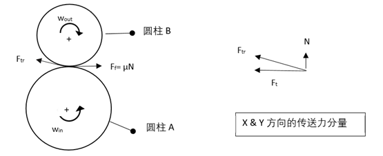
图 1 两个圆柱之间的力传送模型
切线力,Ft 促成圆柱B 旋转。 如果切线力,Ft 大过摩擦力,Ff 将出现移滑状态。而我们是用齿轮来阻止出现移滑状态。
3.1 行星齿轮组传动组合 1
行星架:动力输出
太阳齿轮:动力输入
齿轮圈:锁死
此行星齿轮组组合的力传送模型如下图2。
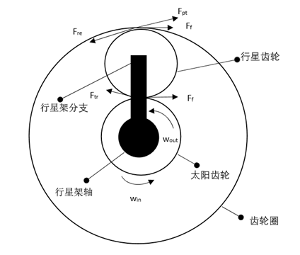
图2 行星齿轮组组合1的力传送模型
Ftr 可以分解为X-Y 方向的分量,如以下图3。
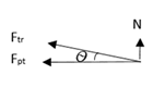
图 3 传送力,Ftr 在X-Y方向的分量
Fpt 是作用于锁死齿轮圈的力,此力造成一个反作用力,Fre 在行星齿轮身上。Fre 可可以分解为X-Y 方向的分量,如以下图4。
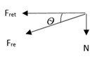
图4 Fre 在X-Y方向的分量
输入扭矩如以下图5。
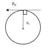
图5 输入扭矩
输入扭矩,𝑇in=𝐹tr . 𝑟s (1)
输出扭矩如以下图6。
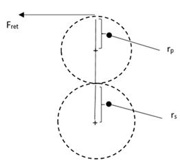
图6 行星架的输出扭矩
输出扭矩,To=Fret . ( 2rp+rs) (2)

把方程 (1) & (2) 代入(3)。Fret 与 Ftr 可当作同等值,因为 Ѳ 很小,(2rp+rs) 是齿轮圈的半径。因此扭矩比也就是齿轮圈的大小除以太阳齿轮的大小。这是符合一家齿轮厂家wittenstein 在 “Made simple:Design and operating principle of a low-backlash planetary gearbox”的视频中第 1分21秒至1分26秒的描述[3]。而角速度比是扭矩比的倒数。

3.2 行星齿轮组传动组合 2
行星架:动力输入
太阳齿轮:锁死
齿轮圈:动力输出
此行星齿轮组组合的力传送模型如以下图7。
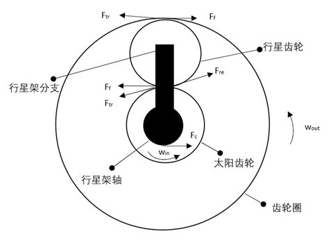
图7 行星齿轮组组合 2的力传送模型
当行星架受动力旋转,Ftr 分别着力于太阳齿轮与齿轮圈。着力于锁死太阳齿轮的转送力,Ftr 是作用于行星齿轮的反作用力,Fre 的由来。此反作用力,Fre 传送至并作用于齿轮圈。这也代表着动力由行星架传送至齿轮圈。
若忽略摩檫力,扭矩比,则:

4 结论
基与本文的力传送原理来替不同组合的行星齿轮组构建模型,不同组合的行星齿轮组的扭矩比与角速度比可以很容易被找到。
参考文献
[1] Robert L. Norton著. Design of Machinery. NY:McGraw-Hill, 2004.495-499;
[2] https://www.kggear.co.jp/en/wp-content/themes/bizvektor-global-edition/pdf/9.9_Calculation-for-Planetary-gear-mechanism_TechnicalData_KGSTOCKGEARS.pdf -不同的行星齿轮组组合可在文中找到。
